.jpg)
Deathmetal Logo
In Rob Scallon’s Video with the band Peeling Flesh they talk about how the ‘Slam’ genre comes out of a self aware ‘horror comedy’ approach to death metal. It...
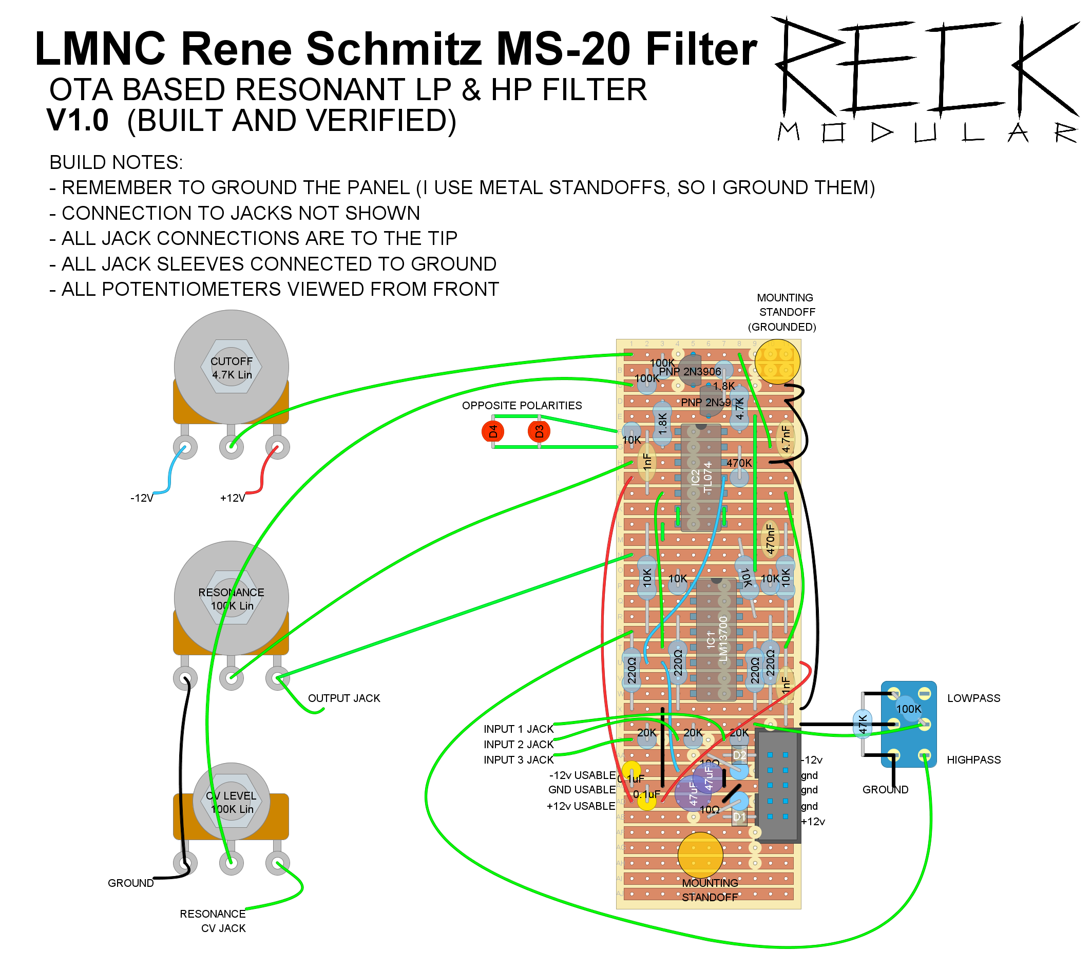
The heavy metal filter of the synth world, the MS-20 VCF is known for its harmonics and resonance the world over. This multi-mode version includes 3 inputs, Low Pass, High Pass, resonance, and CV controlled Cutoff with an adjustable attenuator.
.jpg)
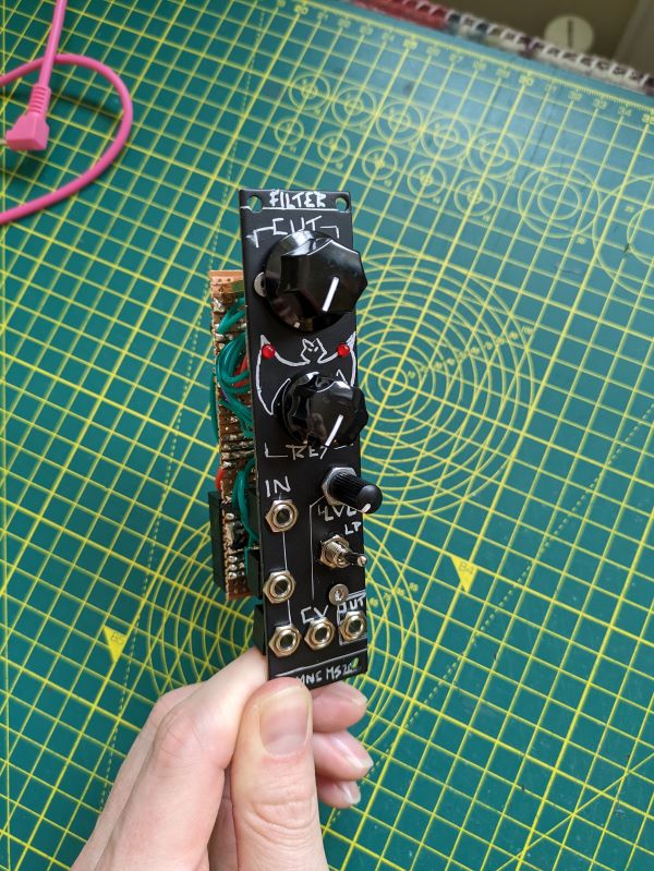
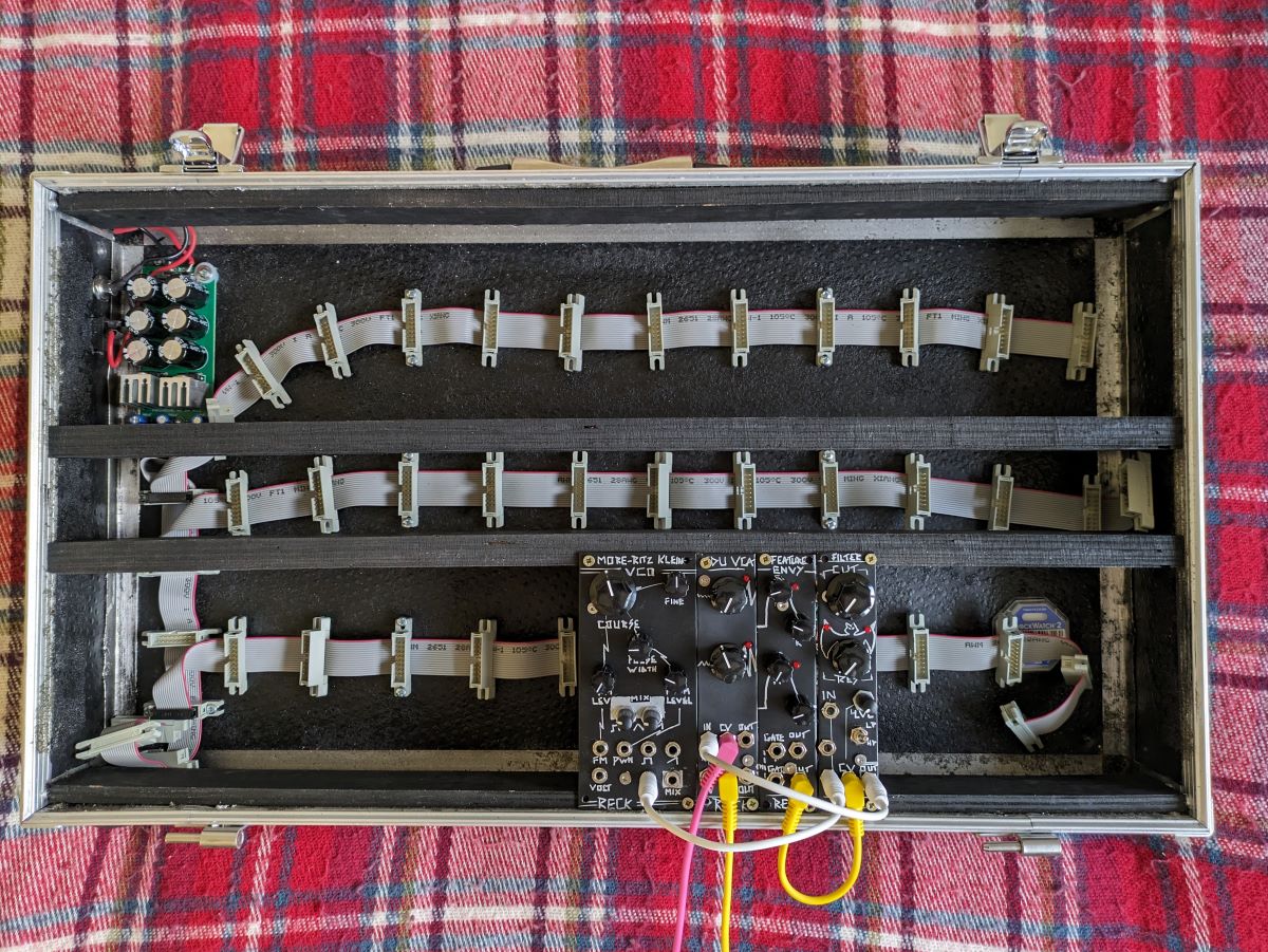
Width: 6 HP
Depth: 40mm
This module is a physically condensed version of Look Mum No Computer’s stripboard layout of his LM13700 based version of René Schmitz’s Late Korg MS-20 Filter.
This filter is an OTA filter based on the late MS-20 LPF. As outlined by Timothy Stinchcombe in his Study of the Korg MS10 & MS20 Fitlers this is a Sallen-Key style filter, whose structure, according to Sound Semiconductor’s - Designing VC VCFs for Synths, is implemented as follows:
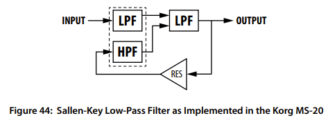
The filtering in this circuit is performed by an Operational Transconductance Amplifier (OTA), configured as a voltage controlled ‘Integrator’ which is filtering the incoming signal. To add potentiometer and voltage control to this, we control the bias of the OTA towards -V and pull it back up with our potentiometer and CV signals (explanation found in Ray Wilson’s book ‘Make: Analog Synthesizers’)
low bias = low transconductance = low cutoff frequency. high bias = high transconductance = higher cutoff frequency.
To improve the roll-off of this filter we add a 2nd filtering stage by running the signal through a buffer (‘A1’ in René’s schematic) and then through a second filter acting as a low pass. This gives us a 2nd order filter. This signal then gets buffered again before passing to our output, plus our resonance circuit.
The resonance circuit here takes the initial abrupt signal change of something like a square wave and uses it to create a feedback loop using op amp ‘A3’ in René’s schematic. This feedback is tamed using some diode clipping in the form of two LEDs.
I won’t steal the schematic and post it here, you can find that on René Schmitz’s website website. There is also a note which explains how to add a switch to allow you to implement High Pass mode, which Look Mum No Computer included in his stripboard layout.
To help with translating between René’s CA3080 version and LMNC’s LM13700 version, Eddy Bergman added the LM13700 pinout to René’s schematic, which can be found here.
As well as condensing the original designs, I made two additional changes:
WARNING - In this layout I am using the 2N3904 NPN and 2N3906 PNP transistors. These have a non-standard pintout (with the E and C pins swapped). Double check your chosen transistors to confirm orientation.
In Rob Scallon’s Video with the band Peeling Flesh they talk about how the ‘Slam’ genre comes out of a self aware ‘horror comedy’ approach to death metal. It...
A vibe coded Autodesk Fusion / Fusion360 add in which allows you to toggle sketch visibility from a timeline or viewport selection
A vibe coded Autodesk Fusion / Fusion360 add-in for managing threaded insert workflows. This tool helps teams identify and mark threaded insert holes using u...
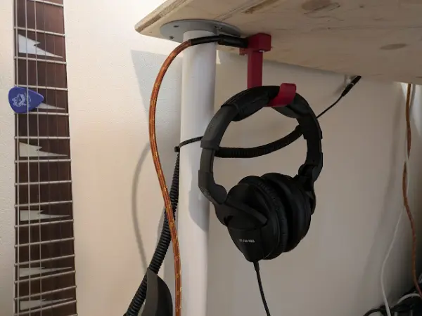
I designed a headphone hook which also provides a place to plug my guitar cable when it isn’t in use.