.jpg)
Deathmetal Logo
In Rob Scallon’s Video with the band Peeling Flesh they talk about how the ‘Slam’ genre comes out of a self aware ‘horror comedy’ approach to death metal. It...
Picture this, you have designed a housing for some delicate electronics, it strikes the perfect balance between aesthetics, protection, and thermal transfer, machined out of a single block of aluminium to keep things simple, but you get your first quote back from the machinist and it is astronomical. After some digging you find out that your beautiful design has one very expensive flaw, a large area of material needs to be removed but you have only allowed space for a small radius in the corners.
.jpg)
.jpg)
Machinists like to perform a cut in the minimum number of operations, this leads them to use the largest machining tool they can to achieve all of the features. If your design only has a 2mm radius in the corners, they will want to use the 2mm (4mm dia) tool. Intuitively, small tools remove less material at a time which means it takes longer to complete the cut. Less intuitively, the deeper a cut is the longer the tool needs to be, and when using small diameter/thin tools this length tends to bend the tool, adding unnecessary wear and stress. The machinist factors this into their quote and the price increases.
.jpg)
| Left: Tool Path for a small diameter milling tool | Right: Milling tool bending due to length required for deep cuts. |
What if they use a large tool for most of the cut and swap to the small one just for the corners? That tool swap takes time and now you are adding wear to two tools. The price stays high.
.jpg)
So, what if they used a large diameter tool? It wouldn’t be able to remove all of the required material in the corners. You could add a process to swap to a smaller tool just for the corners, but that takes additional time and time is money.
.jpg)
Now, what if we approach this design with a DFM (Design For Manufacture) mindset? How would you tweak the profile to achieve the same functionality but allow for just the large cutter to be used?
By flaring the corners you open up your radii significantly whilst leaving all other dimensions untouched. The machinist can use a larger cutter, which takes less time, creates less tool wear under less stress, reducing the price you need to pay.
.jpg)
.jpg)
.jpg) Tool Path for a large diameter milling tool when the design include lobed corners.
Tool Path for a large diameter milling tool when the design include lobed corners.
In Rob Scallon’s Video with the band Peeling Flesh they talk about how the ‘Slam’ genre comes out of a self aware ‘horror comedy’ approach to death metal. It...
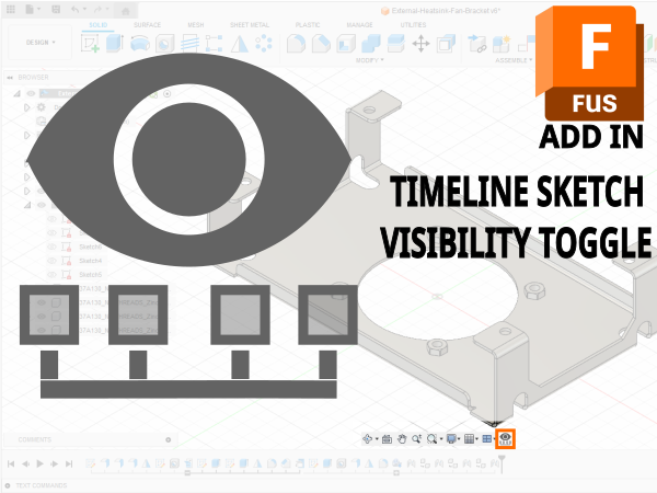
A vibe coded Autodesk Fusion / Fusion360 add in which allows you to toggle sketch visibility from a timeline or viewport selection
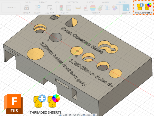
A vibe coded Autodesk Fusion / Fusion360 add-in for managing threaded insert workflows. This tool helps teams identify and mark threaded insert holes using u...
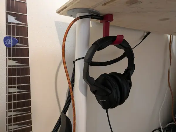
I designed a headphone hook which also provides a place to plug my guitar cable when it isn’t in use.