.jpg)
Deathmetal Logo
In Rob Scallon’s Video with the band Peeling Flesh they talk about how the ‘Slam’ genre comes out of a self aware ‘horror comedy’ approach to death metal. It...
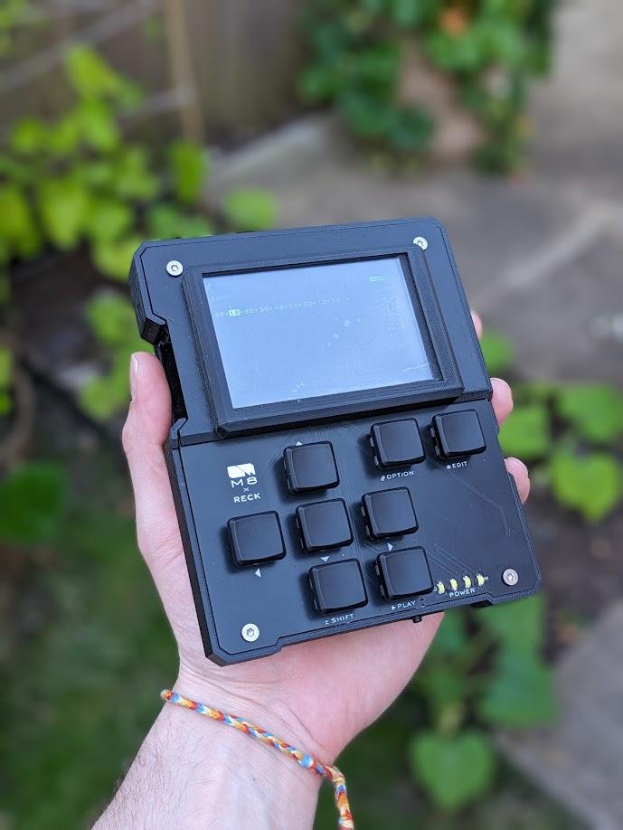
I’m throwing my hat in the ring with this take on the RPi based Headless M8 Tracker Project , giving my product design skills a test and taking the chance to develop my first custom PCB!
![]()
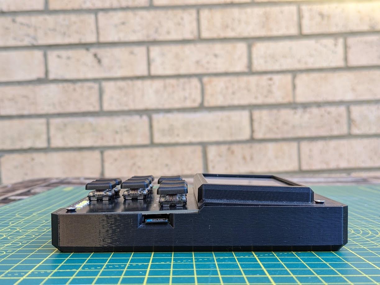
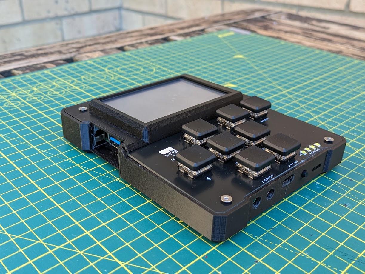
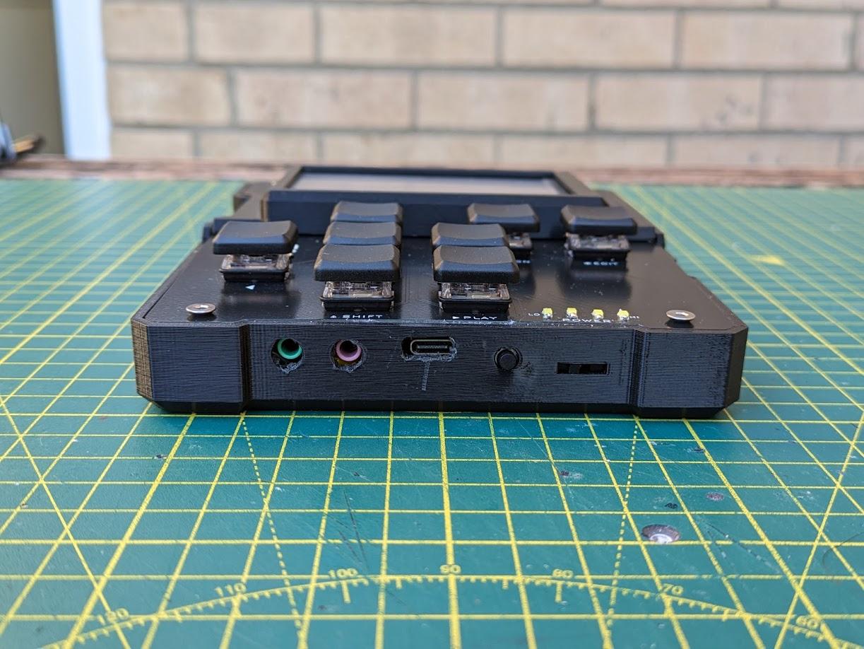
Aesthetically, I wanted this to be an ode to the original, taking design cues from the slick-but-industrial M8 Tracker by Dirtywave. I created an angular shape with visible screws and a structure which hugs the internal components. The PCB front panel exposes the copper tracks under the right light and from the side you can see the inner workings of the key switches. One last touch, a cooling vent in the back in the shape of Dirtywave’s logo. The design had to be a significantly wider due to the much larger battery required to run the RPi, but even with this alternate aspect ratio it maintains it’s relationship to the original. To keep with the portable theme, I included a 1mm clearance above the screen, leaving space to add a clear Perspex covering over the delicate LCD so that you can feel comfort knowing this thing can be chucked in a bag and should survive the trip.
All the components I used plus links to where I got them (note, i’m based in the UK):
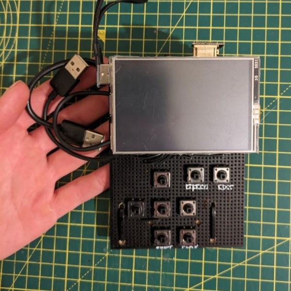
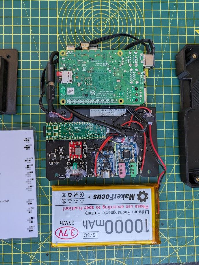
The PCB combines the circuity for the keyboard and charging/power management, and provides a convenient way to mount the usual components from these Raspberry Pi based headless projects, such as the teensy and USB Soundcard. Technically you can get the M8 working much easier way with some stripboard and cable ties (like I did in my prototype build), but once you introduce the components and circuit required for a seamless approach to battery power it gets easier to create a PCB.
![]()
![]()
Stripboard and Cable Tie Prototype
Download links for the V1 and V2 Schematic, Gerbers, and CAD can be found at the bottom of this article!
_Schematic.png)
_PCB.png)
Here is the block diagram for the device:
flowchart TB

	subgraph Charging
		USBC --> TP4056Charger  -.->LiPo
	end

	LiPo --> MomentarySwitch

	subgraph BatteryLevel
		MomentarySwitch --> BatteryLadder
	end

	subgraph AutoPowerDown
		Comparator
	end

	subgraph Keyboard
		8xKeyswitches
	end

	subgraph Power
		LiPo --Diode--> On-Switch
		On-Switch --> StepUp
		USBC --Diode--> On-Switch
		StepUp --5V--> Comparator
	end

	StepUp --5V--> RPi_Power_IN
	Comparator --> RPi_GPIO
	RPi_USBA --> Teensy4.1
	RPi_USBA --> USBSoundCard
	RPi_USBA --> MIDI_IO_Port_1
	RPi_USBA --> MIDI_IO_Port_2
	8xKeyswitches --> RPi_GPIO


	subgraph Peripherals
		Teensy4.1
		Teensy4.1 --> MicroSD
		USBSoundCard
		USBSoundCard --> MonoHeadphones
		USBSoundCard --> MonoMicrophone
		MIDI_IO_Port_1
		MIDI_IO_Port_2
	end

	subgraph RaspberryPi
		RPi_USBA
		RPi_Power_IN
		RPi_GPIO
	end
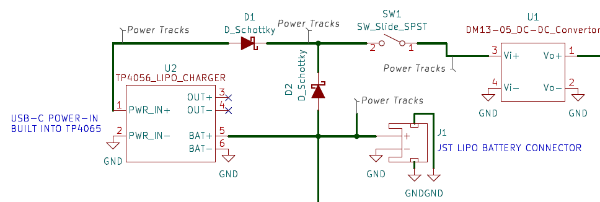
Battery power is the first step to getting this device portable, but anyone who has tried to power and RPi 4 from an old battery bank knows that half of them don’t work, the current draw on these things is insane. This rules out most of your typical hobby grade battery power modules which typically max out at 1A. Instead, I opted for a custom solution powering the RPi directly from a rather large (10000mAh) LiPo battery, one which is capable of handling the 3A max current draw as well the RPi’s thirst for power.
This battery power (which ranges between 3.2-4.2V) is then fed into a 2A capable 5V DC-DC Step-up module before going off to a USB-C Breakout board which is plugged into the RPi’s usual power socket.
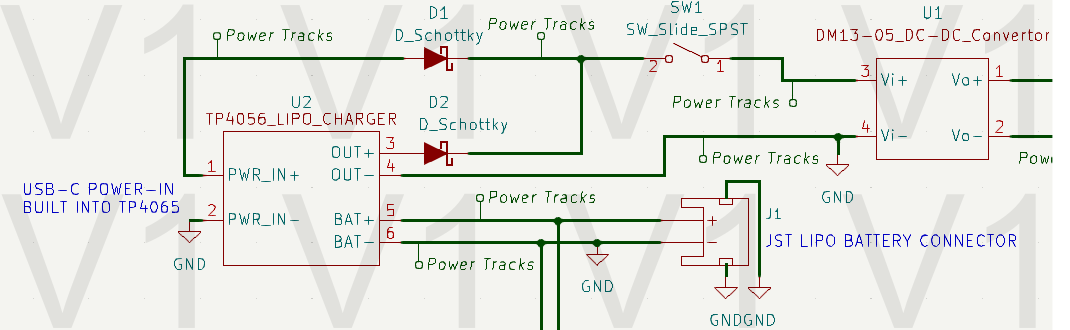
Going for a custom battery solution means that I need to get a little creative with the charging circuit. Ignore the output pins of the TP4056 charging module, they can only provide 1A anyway, instead we connect the battery to two places, the charger and the power circuit (via a schottky diode).
This circuit seamlessly switches between battery and usb power, allowing play to continue no matter where you go.
To find out the battery level you’ve got two options,
To read the battery level on the RPi you would typically connect it to an Analog-Digital-Converter (ADC) and read it from a GPIO pin. The problem is, an ADC would require 4 GPIO pins on the RPi, which I don’t easily have space for due to the pins required for the LCD Display. That leaves us with finding a hardware way of reading it.
I chose to try out a version of the ‘12V Diode Ladder’, modified to work with a single cell LiPo. A 12V Diode Ladder tells you the battery reading using a string of LEDs in series, the voltage level is represented by how many LEDs light up. This circuit works for a 12V battery because each LED has a forward voltage of ~3V, so:
The LiPo Diode Ladder uses the same forward voltage trick, but 3V increments don’t give us enough resolution. Instead, the increments are created using a special low forward voltage schottky diode (with a Vf of 0.4V). The LEDs still have a forward voltage of ~3V, so each LED’s requirements are:
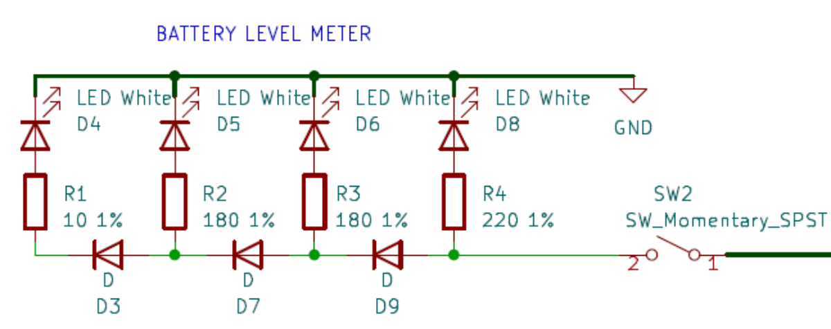
After all of this seemingly logical explanation, the feature doesn't actually work. All four LEDs light up even when battery is low.
There must be a fault in my logic somewhere, if you know what the problem is let me know..
With the battery meter being hardware based, the RPi still has no way of knowing what voltage the battery is at. This creates a problem, no matter how careful you are the battery will drain too far and either the RPi will suddenly shutdown, potentially causing corruption, or the LiPo will drain too low, permanently damaging itself. This calls for another hardware solution.
This circuit utilises an Op Amp wired as an Non-Inverting Schmitt Trigger, configured to pull the output pin LOW once the battery level drops below 3.8V and not return high until it goes above 3.9V (this hysteresis ensures that it doesn’t oscillate back and forth between the two). The output pin is wired into one of the RPi GPIO pins, and GPIONext (the same software used to run the keyboard) registers this as a button press and triggers a shutdown script.
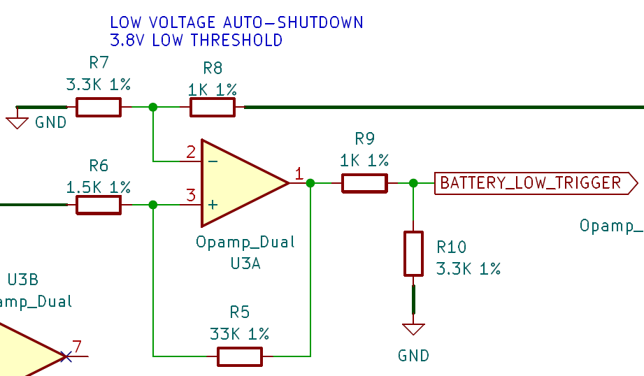
There is a lot of voltage sag on the LiPo Battery during use, meaning that the level regularly drops below the 3.8V threshold, even though it isn't actually that low. This causes the autoshutdown to trigger, even when fully charged
Realistically, the solution to this is software. Creating an autoshutdown trigger which waits for the low voltage signal to last for more than 10 seconds would make this feature work.
For now, I haven't bothered to implement this
For the pin to work, you need to program a command in GPIOnext. Bind the command to ‘Pin 29’, and enter the following command:
sleep 5 && shutdown now
sleep 5 gives the RPi time to finish processing the button press so that GPIOnext doesnt get in the way of shutdownshutdown now is pretty obvious….There are two ways that you could go about doing this:
gpionext config toolFor option 2 you would do the following:
cd ~/gpionext/config
sqlite3 config.db
insert into GPIOnext values(98, 'Commands', 'Low Battery', 'COMMAND', 'sleep5 && shutdown now;', '29');
The values in this entry are:
Now, exit sqlite3. If all went well, after a reboot you will now be able to see your command listed in the GPIOnext configurato tool under the commands section.
Huge thank you to mholgatem, the author of GPIOnext, for the explanation of how to perform this rather non-standard implementation! Github convo found here
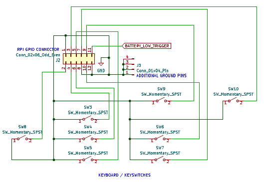
Inspired by ijnekenamay in their M8 Headless Staging project, the keyboard here is simply 8 keyswitches, each of which pull a different RPi GPIO pin LOW. This is then read by a program on the RPi called GPIOnext, which converts these presses into ‘gamepad’ controls which the RPi can register.
GPIOnext can also trigger scripts, which comes in handy for adding the ability to either exit the M8 software and return to the terminal, or to run a shutdown script to safely exit the program and close down the RPi.
When I designed V1 of the PCB, I had taken a rather optimistic approach and assumed that I would be able to solder things such as the slide switch, momentary button, and TP4056 Charging Board directly to surface mount pads, oh boy was I wrong. I knew it would be unconventional, but in reality the surface mount pads are held onto the board fairly weakly and caused me grief.
To get around this, I ended up using hot glue to hold some components in place, and soldered flying leads to earlier points in the circuit to connect the TP4056. This worked well, I should have planned to do this from the start!
It even worked for the slide switch, which I had completely mismodeled in the housing and was sitting about 10mm too low. One large pile of hot glue later and it lines up pretty well.
The other big Issue with the V1 PCB was that I hadn’t expected to need to use the custom power/charging method that I describe above. Instead, I was planning on using the TP4056 in its typical configuration, with the output pins providing power to the RPi. Once I realised that this couldn’t output enough current to boot the Pi I switched to the updated schematic, which was a super easy modification to the existing V1 PCB.
There is nothing special about my software install, I simply copied the main guides out there:
I’m happy with how the project came out, even if I wouldn’t recommend others building it unless they are willing to do some DIY. The V1 PCB wasn’t perfect and took a bit of jank to fix , but I’ve got to admit it looks damn good! Plus, I finally took the leap to learn how to make PCB’s and it worked first time, even if my circuit did have mistakes.
Great project, I’m super excited to play this thing!
Using the files below, you've got two options really:
1. Use the V1 PCB and modify it like I did (I have 4 of these spare, hit me up on my Contact Page if you are interested and I'll post one over
2. Use the V2 PCB files, but note that I never actually used them myself so I haven't tested that everything is cool.
If you do make a version of this, let me know!
M8_Headless_Display_Cover_V1.step
Requires the mods made in V2
M8_Headless_PCB_Gerbers_v1.2.zip
M8-Headless-PCB-V1(KICAD-Project).zip
M8_Headless_PCB_V2(unchecked).pdf
M8-Headless-PCB-V2(KICAD-Project).zip
In Rob Scallon’s Video with the band Peeling Flesh they talk about how the ‘Slam’ genre comes out of a self aware ‘horror comedy’ approach to death metal. It...
A vibe coded Autodesk Fusion / Fusion360 add in which allows you to toggle sketch visibility from a timeline or viewport selection
A vibe coded Autodesk Fusion / Fusion360 add-in for managing threaded insert workflows. This tool helps teams identify and mark threaded insert holes using u...
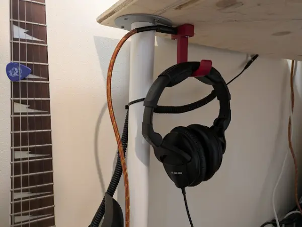
I designed a headphone hook which also provides a place to plug my guitar cable when it isn’t in use.